
PLUMRIDGE • INTEGRATION ROADMAPS
Heavy-Duty Technical Roadmap
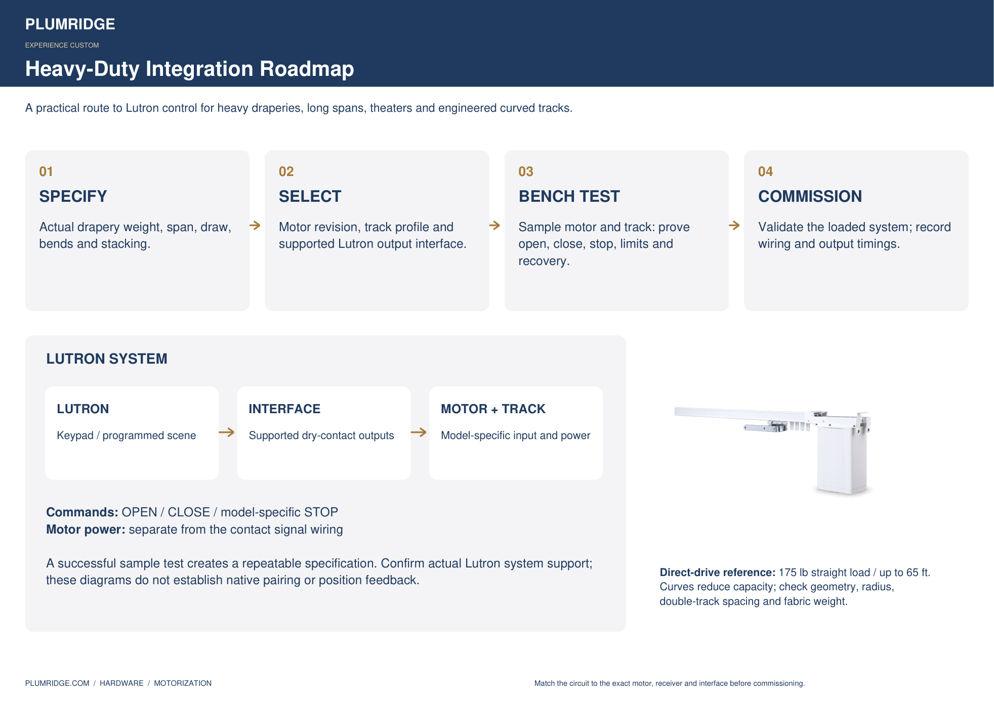
A technical route for heavy draperies, long spans, theaters and engineered curved tracks, with all supplied circuit plates and a sample-track testing plan.
The integration roadmap
 Control & Wiring Diagrams · 8 pages
Why heavy-duty integration matters
A validated heavy-duty motor interface can open opportunities for heavier fabrics and longer runs where the required load or track geometry exceeds the selected alternative system. Model 475 is referenced at 175 lb straight load and up to 65 ft. Curved capacities vary with geometry; a template, load check and double-track spacing review remain part of the specification.
If the integrator believes the selected interface can work, purchasing a sample track and motor provides a concrete way to test the complete route before specifying a large installation.
Wiring and motor-specific stop behavior
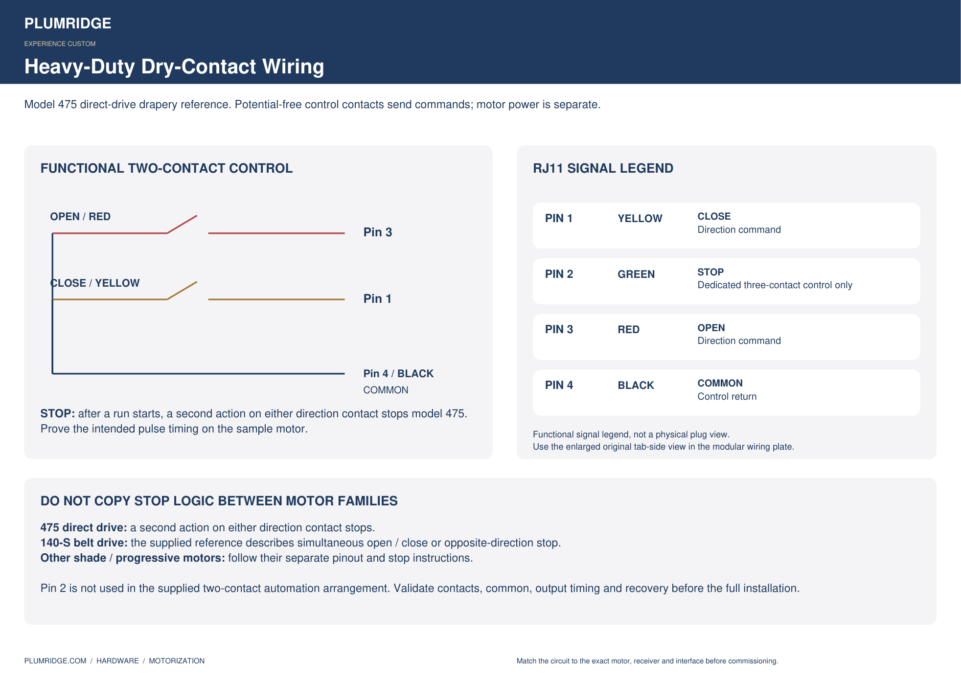
| Model 475 drapery signal | RJ11 pin / color |
|---|---|
| Close | 1 / yellow |
| Dedicated stop | 2 / green; not used by the two-contact automation scheme |
| Open | 3 / red |
| Common | 4 / black |
Model 475 starts with a direction contact action and stops with a second action on either direction contact. Other motor families use different logic. Use the source connector orientation and prove the exact timing on the sample. Motor power is separate from dry-contact signaling.
Modular connector and wall-control wiring
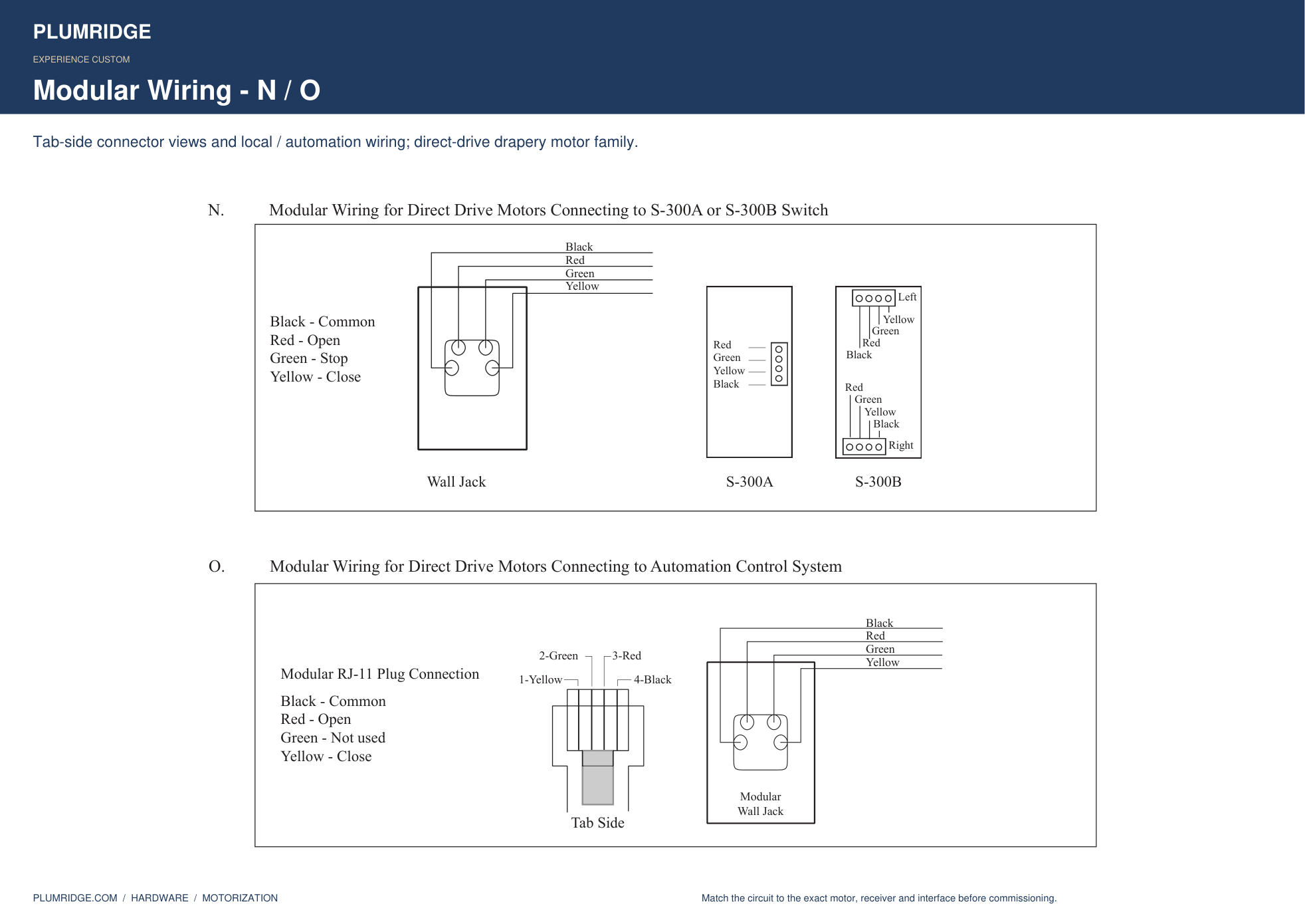
Connector orientation and original circuit geometry are preserved in the enlarged reference. The printable diagram set also includes individual, grouped, local and automation circuit alternatives.
Sample-track testing roadmap
| Test | Record the result |
|---|---|
| Hardware and geometry | Motor revision, receiver, track profile, draw, curves and actual fabric load. |
| Direction and stop | Open, close and mid-travel stop through the intended Lutron device. |
| Repeat commands | Same-direction and opposite-direction actions while moving. |
| Limits and clearance | Stacking, bend travel, double-track clearance and motor access. |
| Recovery and cycling | Behavior after power / controller restart and repeated loaded cycles. |
All diagrams, indexed
These links open the matching chapter of the technical PDF. The PDF also has bookmarks for every original source page.
| Source set | PDF pages |
|---|---|
| Track sections, carrier arrangements, control photos and A–O circuit plates | 7–25 |
| Automation pinouts and alternative RF / network references | 26–31 |
| QSE-IO mounting, terminals, wiring and operating modes | 32–41 |
| Wireless dry-contact reference | 42–48 |
| Curved track shapes, all nine detailed layouts and load comparison | 49–58 |
QSE-IO and the supplied legacy RadioRA 2 visor controller are separate interface references. Compatibility, output ratings and programming must be confirmed for the actual Lutron system. RF alternatives do not establish native Lutron compatibility.
Return to the product overview